Bosch Electronically Controlled Distributor Injection Pump
Fuel system schematic for an electronically controlled distributor injection pump: I, fuel tank; 2, fuel filter; 3, VE pump; 4, injection nozzle with a needle motion sensor; 5, solenoid valve for injection timing; 6,control collar; 7, timing device; 8,feed pump.
The Robert Bosch VE distributor/rotary injection pump is available with one of two mechanical governors to control the speed and response of the engine. These two types of governors and their functions are:

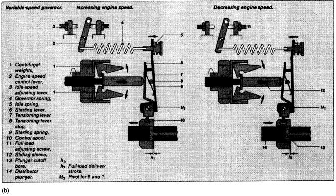
1. Variable-speed governor: controls all engine speed ranges from idle up to maximum rated rpm. With this governor, when the throttle lever is placed at any position, the governor will maintain this speed within the droop characteristics of the governor. The variable-speed governor and its operation are illustrated in Figures 19-77a and 19-77b with its actual location in relation to the other injection pump components being clearly shown in Figure 19-68.

2. Limiting-speed governor: sometimes known as an idle and maximum speed governor since it is designed to control only the low- and high-idle speeds (maximum rpm) of the engine. When the throttle lever is placed into any position between idle and maximum, there is no governor control.Any change to the engine speed must be determined by the driver/operator moving the throttle pedal. This governor is shown in Figure 19-77c.

The variable-speed governor can be used on any application where all-range speed control is desired such as on a stationary engine or on a vehicle that drives an auxiliary power takeoff (PTO).
|


![]()


