Diesel Engine Lucas CAV Fuel Pump
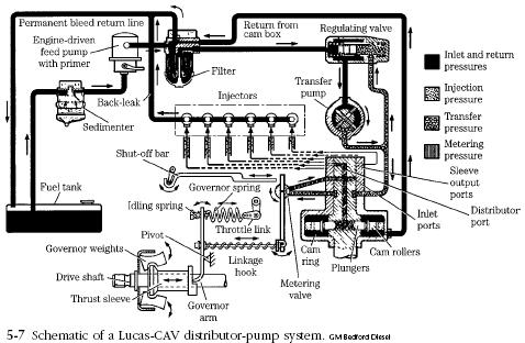
Figure 5-7 illustrates a CAV system for medium trucks. The engine-driven feed pump moves fuel from the tank to the filter and regulating valve. Fuel then passes to the transfer pump and, from there, to the inlet side of the distributor pump for pressurization and injection. As explained below, the regulating valve throttles the injection pump during low-speed operation. Surplus fuel returns to the tank through low-pressure lines.

lucas CAV schematic Diesel Engine Lucas CAV Fuel Pump
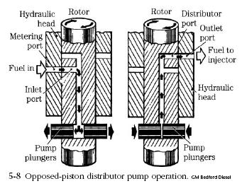
A pair of cam-driven plungers, mounted on the pump rotor and turning with it, generate injector pressure (Fig. 5-8). During the inlet stroke the plungers move outward under pressure from fuel entering through the inlet (or metering) port. As the rotor continues to turn, the inlet port is blanked off by the rotor body and one of the outlet ports is uncovered.

opposed piston pump Diesel Engine Lucas CAV Fuel Pump
As the outlet port is uncovered, the internal cam, acting through rollers, forces the plungers together. Fuel passes through the port for injection. Fuel that slips by the plungers returns to the filter.
The amount of fuel delivered per plunger stroke is determined by the regulating valve (upper right in Fig. 5-7) that is controlled by the accelerator pedal and the centrifugal governor. At low engine speeds, the regulating valve limits the pressure of fuel going to the transfer pump and into the injection pump. Because the pump plungers are driven apart by incoming fuel, their outward displacement is determined by transfer-pump pressure. As engine speed and/or load increase, the regulating valve increases fuel pressure to force the pump plungers further apart. Unlike Bosch inline pumps, which throttle by varying the effective stroke, the Lucas/CAV unit varies the actual stroke. |


![]()


